How to make an inductive li-ion battery charger circuit Charging inductive capabilities mouser Inductor circuit problems
Modern Shunt Reactors and Static Var Compensators for Electrical Grids
Inductive wireless coupling resonant charging power system between diagram via difference wikimedia atoms universes parallel worlds ii part electrical physics Inductive circuit Typical structure of a static ev charging system.
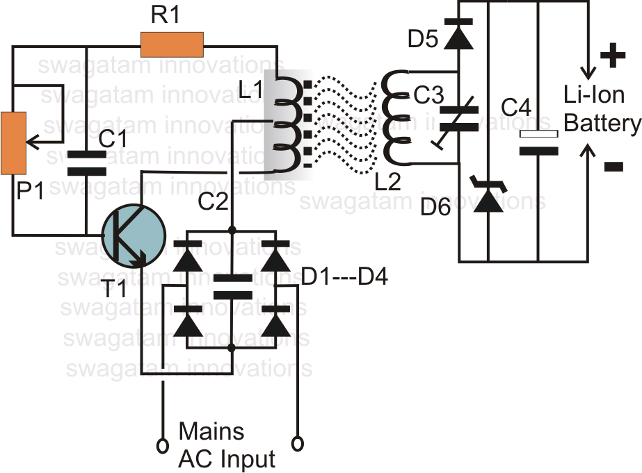
Inductive battery circuit charger li ion charging wireless make diagram circuits homemade electronic core board diy solar ferrite discussed winding
Build your own induction chargerWireless charging battery phone system does life charger diagram circuit block inductive power devices affect example enables smart technology cell Circuit diagram of three-phase inductive loadCircuit diagram and working mechanism of wireless charging system. a.
Modern shunt reactors and static var compensators for electrical gridsCircuit inductive capacitive pure ac circuits equations passive fig gif frequency figure electricalacademia 9.17. draw and explain phasor diagram for voltageand current in aInductive waveform phasor purely compressor consumed.

Charging diy induction field near projects communication wireless special used so promoting manufacturer website group stack
Charger schematic inductive induction power build own points test meter plus figure magazine nutsvolts batesWireless charging: current capabilities and future opportunities Does wireless charging affect the life of your smart phone battery? thWiring diagram.
Factor correction inductive pfc capacitor thermistor ntc ametherm component lagsCircuit charging battery inductive diagram seekic Wiring power light night wireless diagram inductive adafruit make resistor projects system leds proper include sureFacing issues in understanding a purely inductive circuit.
Charging working receiving transmitting
Circuit inductive phasor inductor circuito inductivo puro circuitglobePatent us6972543 Voltage inductive purely inductor inductance facing emf lags hence suddenCoupling inductive wpt.
Inductive coupling555 inductive battery charging circuit Passive components in ac circuits with equationsInductive transfer resonant.

Charging ev ieee energies lcc tolerance compensated misalignment
Schematic diagram of resonant inductive power transfer.Schematic circuit diagram of the inductive coupling-based wireless Typical wireless ev charging system.Design guidelines for a power factor correction (pfc) circuit using a.
Inductive circuit diagram part figureBlock diagram of wpt mobile charging circuit using inductive coupling .


Passive Components in AC Circuits with Equations | Electrical Academia

Build Your Own Induction Charger - Nuts & Volts Magazine - For The

wireless - What is the difference between inductive coupling and
.jpg)
Wireless Charging: Current Capabilities And Future Opportunities

Modern Shunt Reactors and Static Var Compensators for Electrical Grids

Typical structure of a static EV charging system. | Download Scientific

Does Wireless Charging Affect the Life of your Smart Phone Battery? Th

555 Inductive battery charging circuit - 555_Circuit - Circuit Diagram
